When measuring gas with a vortex flowmeter, temperature and pressure compensation is necessary for accurate measurement. The volume of gas varies greatly with temperature and pressure, and not compensating can lead to serious errors in trade settlement. Saturated steam can be compensated individually, superheated steam requires dual compensation, and liquids usually do not require compensation. The integrated internal compensation is more convenient, while the split external compensation is flexible.
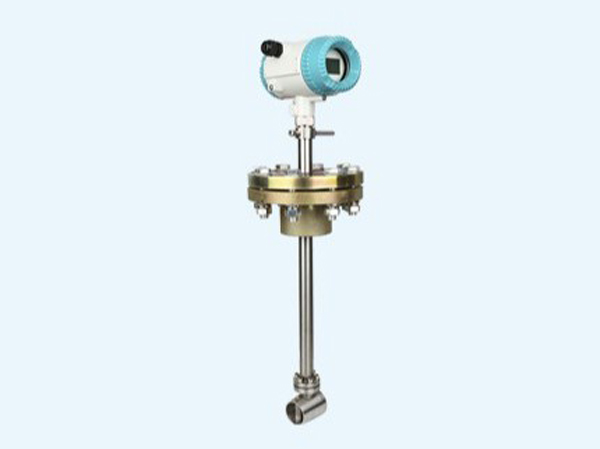
The vortex flowmeter itself measures the volumetric flow rate under operating conditions (the actual gas volume under pipeline temperature and pressure), and the gas volume is greatly affected by temperature and pressure; Temperature and pressure compensation is the process of converting the volumetric flow rate of operating conditions into the volumetric flow rate (in standard Nm ³/h) or mass flow rate under standard conditions, for accurate measurement.
Simple understanding: As gas pressure increases and temperature decreases, the volume of gas of the same weight will decrease. Only measuring the working condition volume, the reading becomes inaccurate when the pressure and temperature change.
- When temperature and pressure compensation must be used only for gases (air, steam, natural gas, etc.)
Liquid: Liquid is minimally affected by temperature and pressure, and generally does not require temperature and pressure compensation;
Saturated steam: can only be used for pressure compensation, or only for temperature compensation (saturated steam temperature and pressure correspond one-to-one);
Overheated steam: both temperature and pressure need to be compensated for;
Ordinary gas: temperature and pressure dual compensation. - The core principle is based on the ideal gas state equation:
Actual working pressure and temperature of the pipeline
Volume flow rate measured by vortex street under operating conditions
Standard state (standard condition, usually 0 ℃ or 20 ℃, 101.325kPa)
The volume flow rate of the standard condition obtained after compensation
Vortex street measurement (V1), connected to on-site temperature and pressure transmitter signals, instrument internal calculation, output standard flow rate or mass flow rate. 3. What are the problems without temperature and pressure compensation
The pressure increases, the gas is compressed, and the volume of the same mass of gas under working conditions decreases, resulting in a smaller reading on the flow meter;
As the temperature rises, the gas expands, and the volume of the same mass of gas under working conditions increases, the flow meter reading tends to be larger;
When used for trade settlement and energy consumption statistics, the error can be significant and cannot be used for measurement at all. - Two compensation implementation methods
Internal compensation (integrated vortex street): The vortex street body integrates temperature and pressure sensors, directly outputs standard flow rate, and has simple wiring;
External compensation (split): The vortex street only outputs pulses/4-20mA operating flow rate, with external temperature and pressure transmitters connected, and DCS/PLC connected for compensation calculation.
Supplementary differentiation
Operating flow rate: The actual volume inside the pipeline at this moment (Nm ³) is not the operating condition! Nm ³ is the standard condition)
The standard flow rate Nm ³/h is the gas volume at 0 ℃ and 101.325kPa, which is the universal unit of gas measurement
Temperature and pressure compensation refers to the technology of automatically converting the “working condition volume flow rate” measured by a flow meter into “standard condition volume flow rate (Nm ³/h)” or “mass flow rate (kg/h)” by real-time collection of gas temperature and pressure, using the gas equation. The core purpose is to eliminate the influence of temperature and pressure fluctuations on gas density and ensure accurate measurement.
Why do we need temperature and pressure compensation
The gas turbine flowmeter directly measures the volumetric flow rate under operating conditions (i.e. the actual volume at the current temperature and pressure). But gases have compressibility, and their density varies significantly with temperature and pressure:
Temperature increase → gas expansion → density decrease → decrease in mass corresponding to the same volume
Pressure increases → gas is compressed → density increases → mass corresponding to the same volume increases
If no compensation is made, when the operating conditions deviate from the design conditions, the flow meter reading cannot truly reflect the actual gas consumption, which will cause significant errors in trade settlement and energy management.
Our company’s gas turbine flowmeter in Xiamen is equipped with temperature and pressure compensation
Compensation principle and calculation
The core basis is the ideal gas state equation:
PV = nRT
From this, the conversion relationship between operating condition density and standard condition density can be derived:
ρ₁ = ρ₀ × (P₁/P₀) × (T₀/T₁)
ρ₁: Gas density under working conditions (kg/m ³)
ρ₀: Gas density under standard conditions (kg/m ³)
P ₁: Absolute pressure under working conditions (MPa)
P ₀: Standard atmospheric pressure (0.1013 MPa)
T ₁: Absolute temperature under working conditions (K)
T ₀: Standard temperature (usually taken as 293.15K, i.e. 20 ℃)
The flow integrator collects temperature and pressure signals in real time, calculates the current density using the above formula, and then converts the operating volume flow rate into standard flow rate or mass flow rate.
implementation method
Integrated temperature and pressure compensation type: The flowmeter integrates temperature sensors, pressure sensors, and intelligent integrators internally, automatically completes compensation calculations, and directly outputs standard flow rate. Compact structure, suitable for on-site installation
Split type temperature and pressure compensation: Flow meters, temperature transmitters, and pressure transmitters are installed separately, and the signals are uploaded to the PLC or DCS system for compensation calculation. Suitable for situations with existing control systems, it has higher flexibility.
Compensation requirements for different media
Examples of actual impacts
Taking compressed air as an example: under the working conditions of 0.6 MPa and 80 ℃, the air density is about 5.92 kg/m ³; At standard conditions (20 ℃, 101.325 kPa), the density is only about 1.204 kg/m ³. If the flow meter measures a working condition flow rate of 100 m ³/h and calculates directly based on the standard density without compensation, the error will be very large. After temperature and pressure compensation, the system will automatically convert it into accurate standard flow rate (about 492 Nm ³/h) and mass flow rate (about 592 kg/h)
Vortex flowmeter is a velocity flow meter based on the principle of “Karman vortex street” fluid mechanics, mainly used for accurately measuring the volume flow or mass flow of gases, liquids, and vapors in pipelines.
Working principle
Insert a non streamlined column vertically into the pipeline (known as a vortex generator, commonly a triangular or trapezoidal column). When a fluid flows through it at a certain speed, two columns of regular vortices with opposite rotation directions will alternate on its downstream sides, forming the so-called “Karman vortex street”.
The release frequency of vortices is directly proportional to the average flow velocity of the fluid, and the core formula is:
f = St × v / d
f: Vortex separation frequency (Hz)
St: Strouhal number (constant within a certain Reynolds number range)
v: Average fluid velocity (m/s)
d: Characteristic width of vortex generator (m)
The vortex frequency is detected by piezoelectric or capacitive sensors, converted into pulse signals, and then the instantaneous flow rate and cumulative flow rate are calculated by the signal processing unit.
Basic structure of vortex flowmeter
vortex flowmeter mainly consists of the following parts:
Vortex generator: the core component that generates Karman vortex streets
Sensor probe: detects vortex frequency (piezoelectric, capacitive, strain gauge, etc.)
Signal processing unit: converts frequency signals into flow data and outputs it
Main characteristics of vortex flowmeter
No movable parts: sturdy structure, high reliability, long service life, and minimal maintenance
Range width ratio: generally up to 10:1 or more, some models can reach 15:1 or even higher
High measurement accuracy: usually up to ± 0.5%~± 1.0%
Small pressure loss: Compared to orifice flow meters, it has a significant energy-saving effect
The output signal is proportional to the flow rate: the pulse frequency signal is not affected by changes in fluid temperature, pressure, or density
Widely applicable media: the same instrument can measure gases, liquids, and vapors
Limitations of vortex flowmeter
Not sensitive to low-speed fluids and not suitable for fluids with low Reynolds numbers (Re ≤ 2 × 10 ⁴)
Not suitable for high viscosity fluids
It is not suitable to install in places with strong vibration, otherwise it may cause “locking” phenomenon and lead to measurement abnormalities
There are certain requirements for the front and rear straight pipe sections (usually 10D in the front and 5D in the back)
Main functions and application areas of vortex flowmeter
Steam metering: measuring the flow rate of saturated steam and superheated steam, widely used for energy accounting and cost control in heating, power plants, and chemical industries
Gas measurement: flow measurement of industrial gases such as compressed air, natural gas, nitrogen, oxygen, etc
Liquid measurement: water (boiler feed water, cooling water), low viscosity oil products, chemical raw materials, etc
Energy management: providing accurate data support for energy trade settlement, energy conservation and consumption reduction
Environmental protection: monitoring the discharge flow of smoke, wastewater, etc
Process control: achieving material ratio and process control in industries such as chemical, pharmaceutical, and food