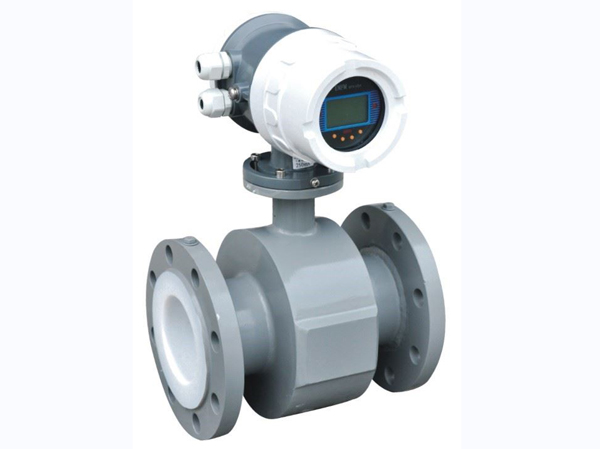
Flange-mounted turbine flowmeter are versatile flow measurement instruments
In industrial production and process control, the precise measurement of fluid flow is critical to ensuring efficiency, safety, and quality. Among these, the flange-mounted turbine flow meter—a classic and widely used flow measurement instrument—plays a vital role in numerous fields due to its unique operating principle and reliable performance. Rather than relying on complex electronic image recognition or advanced algorithms, it utilizes precise mechanical structures and fluid dynamics principles to achieve stable measurement of the volumetric flow rate of liquids or gases.
Working Principle: When the fluid drives the “mini windmill”
To understand a flanged turbine flowmeter, we can start with a simple analogy: it is like a “mini windmill” immersed in a fluid pipeline.
- Core Component—Turbine Rotor: At the center of the flowmeter’s measuring chamber is an axial-flow impeller, known as the turbine rotor. Its blades are precision-engineered and machined to a specific helix angle.
- Fluid Drive and Rotation: When fluid (which can be water, oil, chemical liquids, or various gases) flows through the flowmeter, it impacts the sides of the turbine blades. According to the principles of fluid dynamics, the fluid exerts a thrust on the blades, causing the turbine rotor to rotate around its axis.
- Relationship Between Rotational Speed and Flow Rate: The turbine’s rotational speed is not arbitrary; there is a definite, linear proportional relationship between its rotational speed and the fluid velocity (i.e., volumetric flow rate) flowing through the pipe. The faster the fluid velocity, the greater the thrust on the blades, and the higher the turbine’s rotational speed.
- Signal Generation and Conversion: On the exterior of the flowmeter housing, at the position corresponding to the turbine blades, a signal detector—either electromagnetic or radio-frequency—is installed. Whenever a turbine blade rotates past the detector, it cuts through magnetic lines of force or alters the electromagnetic field, thereby generating a pulsed electrical signal. Thus, each rotation of the turbine produces a specific number of pulses.
- Flow Calculation: Finally, by measuring the pulse frequency generated per unit of time, the internal converter or the connected display and totalizer can accurately calculate the fluid’s instantaneous flow rate and cumulative flow. This “flow-frequency” relationship is rigorously calibrated before the instrument leaves the factory.
Key Structural Features: A Combination of Durability and Precision
The term “flange” directly highlights its key installation characteristic. A flange is a disc-shaped component commonly used in piping connections, secured to a mating flange on the pipe via bolts.
- Flange Connection Method: This design allows the flowmeter to be securely installed in series within a piping system, offering excellent sealing performance and high pressure resistance. It is particularly suitable for medium- to high-pressure, large-diameter industrial piping environments, and installation and removal are relatively convenient.
- Main Structure: Typically consists of the following major components:
- Housing: Serving as the pressure-bearing main body, it is usually made of sturdy materials such as stainless steel and forms the fluid passageway internally.
- Turbine Rotor Assembly: Includes the turbine blades, shaft, and bearing system; this is the core moving component. The material and design of the bearings directly affect the instrument’s service life and lower measurement limit.
- Signal Transducer: Responsible for converting mechanical rotation into an electrical signal.
- Preamplifier: Some models integrate a signal amplification and conditioning module to ensure a more stable output signal and enhanced resistance to interference.
- Flow Guides: Flow guide structures are typically designed in front of and behind the turbine. The front flow guide serves to straighten the flow, eliminate fluid vortices, and create a smoother flow pattern, ensuring the fluid strikes the turbine blades at an optimal angle to improve measurement accuracy. The rear flow guide aids in support and stabilization.
Performance Advantages and Application Considerations
Every measurement technology has its most suitable application scenarios, and flanged turbine flowmeters are no exception.
Their notable advantages include:
- High accuracy and good repeatability: Within the specified flow range, they achieve high measurement accuracy and excellent consistency in repeated measurements, which is critical for trade settlement and process control.
- Rapid Response: Due to the turbine’s low inertia, it responds very quickly to flow changes with a short time constant, making it suitable for measuring pulsating flows or rapidly changing processes.
- Wide Measurement Range: Its effective measurement range (i.e., the ratio of maximum flow to minimum flow) is relatively wide, offering strong adaptability.
- Digital Signal Output: It directly outputs a pulse frequency signal proportional to the flow rate, offering strong resistance to interference. This facilitates remote transmission and integration with computer systems without the need for analog-to-digital conversion.
- Compact Design and Low Pressure Drop: The optimized design of the flow channel and turbine minimizes the pressure drop caused by fluid flow, helping to reduce system energy consumption.
However, the following factors must be considered during actual selection and application:
- Influence of fluid properties: Measurement accuracy is sensitive to parameters such as fluid density and viscosity. When the same flowmeter is used to measure liquids of different viscosities, its measurement characteristic curve (instrument coefficient) will vary; typically, calibration or viscosity compensation is required based on the actual measured medium.
- Cleanliness requirements: The turbine rotor is a precision moving component. Particles, fibers, and other impurities in the fluid may cause bearing wear, jamming, or even blade damage, affecting measurement accuracy and service life. Generally, the measured fluid must be relatively clean, and a filter should be installed upstream.
- Installation requirements: To ensure measurement accuracy, sufficiently long straight pipe sections are required upstream and downstream (typically at least 10 times the pipe diameter upstream and at least 5 times the pipe diameter downstream) to create a stable and fully developed velocity profile. During installation, ensure that the pipeline is coaxial with the flowmeter to avoid stress.
- Long-Term Operational Stability: Bearing wear is the primary factor affecting long-term stable operation. As the instrument ages, the coefficient of performance may undergo slight drift; therefore, periodic calibration is a necessary measure to maintain accuracy.
Typical Applications
Thanks to their unique characteristics, flanged turbine flow meters are widely used across multiple industries:
- Oil and Chemical Industry: Used to measure the transportation and distribution of crude oil, refined oil products, light hydrocarbons, solvents, and various chemical liquids; commonly employed in tank farm loading/unloading, pipeline transportation, and process blending.
- Natural Gas and City Gas: Gas turbine flow meters, featuring specialized designs and material selections, are widely used in natural gas transmission and distribution, city gate stations, and gas volume trade settlement for industrial and commercial customers.
- Water Supply and Water Treatment: Used for high-flow measurement of raw water and treated water, as well as for monitoring industrial water usage.
- Industrial Process Control: Used as monitoring and control instruments for the flow of liquid raw materials or additives in process flows within industries such as food, pharmaceuticals, and papermaking.
- Research and Testing Systems: Used as standard or reference measurement equipment on fluid test benches requiring high response speed and high repeatability.
Key Considerations for Selection, Installation, and Maintenance
To fully utilize the performance of flanged turbine flow meter, proper selection, installation, and maintenance are essential.
- Key Selection Parameters: Determine the type of fluid (liquid/gas, name), density and viscosity under operating conditions, pipe diameter, operating pressure and temperature, expected minimum, typical, and maximum flow rates, as well as the required measurement accuracy class.
- Installation Precautions: The meter must be installed horizontally, ensuring the rotor shaft is level to guarantee proper bearing lubrication and even force distribution. Ensure the fluid flow direction aligns with the arrow on the meter housing. Strictly adhere to the required upstream and downstream straight pipe sections, and ensure reliable grounding to prevent electromagnetic interference.
- Routine Maintenance: Regularly inspect the condition of the filter and clean it promptly. Monitor whether the operating sounds are normal and observe whether the display is stable. Perform offline or online calibration periodically in accordance with procedures to correct the instrument coefficient and ensure the accuracy and reliability of measurement data.
In summary, the flanged turbine flowmeter is a reliable measurement tool that combines classic mechanical principles with modern signal detection technology. While it is not the highest-quality instrument, it consistently provides a solid data foundation for industrial production in the field of medium-to-high flow rate measurement of clean, stable fluids, thanks to its accuracy, response speed, and reliability. Understanding its operating principles and characteristics, and adhering to proper usage guidelines, is key to ensuring long-term stable and accurate measurement.