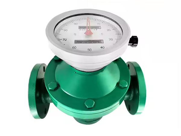
Oval gear flowmeter (also known as displacement flowmeter, gear flowmeter) is a type of volumetric flowmeter with high accuracy in flow meters. It uses mechanical measuring elements to continuously divide the fluid into individual known volume parts, and measures the total flow volume based on the number of times the measuring chamber sequentially and repeatedly fills and discharges that volume part of the fluid. The Oval gear flowmeter can be made of different materials (cast iron, cast steel, 304 stainless steel, 316 stainless steel) and is suitable for flow measurement in industrial sectors such as chemical, petroleum, pharmaceutical, power, metallurgy, and food.
Manufacturer of Diesel Kerosene Viscose Liquid Mechanical Flow Meter
Oval gear flowmeter is a type of volumetric flowmeter used for precise continuous or intermittent measurement of liquid flow or instantaneous flow in pipelines. It is particularly suitable for flow measurement of high viscosity media such as heavy oil, polyvinyl alcohol, resin, etc. The Oval gear flowmeter uses mechanical measuring elements to continuously divide the fluid into individual known volume parts, and measures the total volume of the fluid based on the number of times the measuring chamber is filled and discharged with this volume part of the fluid sequentially and repeatedly.
Working principle of Oval gear flowmeter
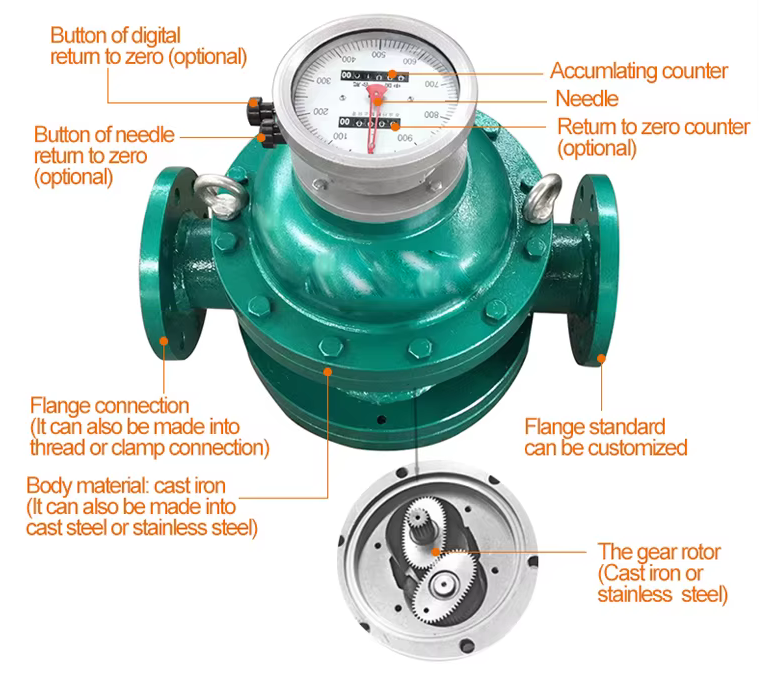
A flowmeter is composed of a measuring box and a pair of Oval gears installed inside the measuring box, forming a sealed lunar cavity with upper and lower cover plates (not absolutely sealed due to the rotation of the gears) as the unit for calculating the primary displacement. When the measured liquid enters the flowmeter through the pipeline, the pressure difference generated at the inlet and outlet drives a pair of gears to rotate continuously, continuously delivering the liquid measured by the initial lunar cavity to the outlet. The product of the number of revolutions of the Oval gear and four times the displacement per time is the total flow rate of the measured liquid (see principle diagram). The flowmeter is mainly composed of a housing, a counter, an Oval gear, and a coupling (divided into magnetic coupling and axial coupling).
The measuring part of the LY-LC and AFLC series Oval gear flow meters is mainly composed of two interlocking Oval gears and their housing (measuring chamber). The Oval gears generate a torque under the action of the pressure difference △ p=pl-p2 of the measured medium, causing it to rotate. At the position shown in (a), due to P1>P2, the resultant torque generated by the action of P1 and P2 causes wheel 1 to rotate clockwise, discharging the medium in the half moon area between wheel 1 and the housing to the outlet and driving wheel 2 to rotate counterclockwise. At this point, 1 is the driving wheel and 2 is the driven wheel. In (b), the middle position is shown, where 1 and 2 are both driving wheels; At the position shown in (c), the resultant torque of P1 and P2 acting on wheel 1 is zero, and the resultant torque acting on wheel 2 causes wheel 2 to rotate counterclockwise and discharge the medium that has been sucked into the half moon volume to the outlet. At this point, wheel 2 is the driving wheel and wheel 1 is the driven wheel, which is exactly opposite to the situation shown in (a). This cycle repeats, with wheel 1 and wheel 2 alternately driven by one to rotate the other, and the measured medium is discharged from the inlet to the outlet in half moon volume units. Obviously, as shown in (a), (b), and (c) of the figure, it only represents that the Oval gear has rotated 1/4 of a revolution. The situation is that the measured medium discharged by the Oval gear has a half moon shaped volume. Therefore, the measured medium mass per revolution of the Oval gear is four times the half moon shaped volume. The volumetric flow rate Q through the Oval gear meteor gauge is: Q=4nυ0
In the formula: n – the rotational frequency of the Oval gear (revolutions per second);
υ 0- Volume of the half moon shaped part (shell)
In this way, under the condition that the half moon product υ 0 of the Oval gear flowmeter is constant, as long as the rotational speed n of the Oval gear is measured, the flow rate of the measured medium can be known.
The display of the flow signal (i.e. the rotational speed n of the Oval gear) of the Oval gear flowmeter has two types: local display and remote display.
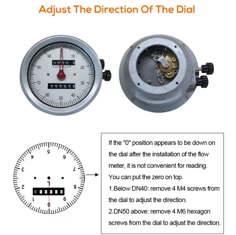
After a series of deceleration and speed ratio adjustment mechanisms, the rotation of the gears is directly connected to the indicator pin on the instrument panel and the total amount is displayed through a mechanical counter.
The remote display is mainly driven by the gear after deceleration to rotate the permanent magnet, so that the contacts of the spring relay close or open synchronously with the rotation frequency of the permanent magnet, thereby emitting a series of electrical pulses to be transmitted remotely to another display instrument
Characteristics of Oval gear flowmeter
Flow measurement is independent of the flow state of the fluid, as the Oval gear flowmeter relies on the pressure head of the measured medium to drive the Oval gear to rotate for measurement.
The higher the viscosity of the medium, the smaller the amount of leakage from the gear and measuring space gap. Therefore, the larger the viscosity of the measured medium, the smaller the leakage error, and the more advantageous it is for measurement.
The Oval gear flowmeter has high measurement accuracy and is suitable for measuring the flow rate of high viscosity media, but it is not suitable for fluids containing solid particles (solid particles can jam the gear, making it impossible to measure the flow rate). If gas is mixed in the measured liquid medium, it can also cause measurement errors.
Application guide for Oval gear flowmeter
Flow measurement is independent of the flow state of the fluid, as the Oval gear flowmeter relies on the pressure head of the measured medium to drive the Oval gear to rotate for measurement. The higher the viscosity of the medium, the smaller the amount of leakage from the gear and measuring space gap. Therefore, the larger the viscosity of the measured medium, the smaller the leakage error, and the more advantageous it is for measurement. The Oval gear flowmeter has high measurement accuracy and is suitable for measuring the flow rate of high viscosity media [1], but it is not suitable for fluids containing solid particles (solid particles can jam the gear, making it impossible to measure the flow rate). If gas is mixed in the measured liquid medium, it can also cause measurement errors. Before installing the Oval gear flowmeter, the pipeline should be cleaned. If the liquid contains solid particles, a filter must be installed upstream of the pipeline; If it contains gas, an exhaust device should be installed. The HI-TOUCHM series Oval gear flowmeter does not have certain requirements for the front and rear straight pipe sections. It can be installed horizontally or vertically. During installation, the Oval gear rotation axis of the flowmeter should be parallel to the ground.
Precautions for using Oval gear flowmeter
1) Cleaning pipelines: Newly installed pipelines need to be cleaned before operation, often followed by flushing with real flow to remove residual welding chips, scale, and other debris. At this point, the front and rear shut-off valves of the instrument should be closed first to allow the liquid flow to pass through the bypass pipe; If there is no bypass pipe, a short pipe should be installed at the instrument position instead.
2) Exhaust gas: Usually, after the solid liquid is swept, there is still a lot of air remaining in the pipeline. With pressurized operation, the air flows through the volumetric flowmeter at a high flow rate, and the movable measuring element may run too fast, damaging the shaft and bearings. Therefore, at the beginning, the flow rate should be slowly increased to allow the air to gradually overflow.
3) Switching sequence of bypass pipe: When the liquid flow enters the instrument from the bypass pipe, the opening and closing should be slow, especially on high temperature and high pressure pipelines. When activated, the first step is to slowly open valve A, allowing the liquid to flow through the bypass pipe for a period of time; Step 2: Slowly open valve B; Step 3: Slowly open valve C; Step 4: Slowly close valve A. Operate in the reverse order as described above when closing. After starting, confirm that there is no excessive flow through the lowest pointer or dial and stopwatch. The optimal flow rate should be controlled at (70-80)% of the maximum flow rate to ensure the service life of the instrument.
4) Check the filter: The filter mesh is most prone to breakage when starting a new line. After trial operation, it is necessary to check whether the mesh is intact in a timely manner. At the same time, when the filter screen is clean and free of dirt, record the two parameters of pressure loss under common flow rate. In the future, there is no need to remove and check the blockage of the filter screen, and the degree of increase in pressure loss can be used to determine whether cleaning is necessary.
5) Measuring high viscosity liquids: Used for high viscosity liquids, usually heated to make them flow. After the instrument is stopped, the internal liquid cools and thickens. When it is restarted, it must be heated until the viscosity of the liquid decreases before allowing the liquid to flow through the instrument, otherwise it will bite the movable measuring element and damage the instrument.
6) Add lubricating oil: Lubricating oil must be added before using PDF for gas and other purposes, and the level gauge for lubricating oil inventory should be checked regularly during daily operation.
7) Avoid sudden flow changes: When using a gas waist wheel flowmeter, attention should be paid to avoiding sudden flow changes (such as using a quick opening valve). Due to the inertia of the waist wheel, sudden flow changes will generate significant additional inertial forces, causing damage to the rotor. When used as a detection instrument for a control system, if the downstream control suddenly cuts off the flow, the rotor cannot stop for a moment, resulting in a compressor effect, an increase in downstream pressure, and then backflow, sending an error signal.
8) Steam used for flushing pipelines is prohibited from passing through Oval gear flow meters.