Gas turbine flow meters are mainly used for measuring the flow rate of natural gas, air, nitrogen and other medium fluids in industrial pipelines. When measuring the volumetric flow rate under working conditions, they are almost unaffected by parameters such as fluid density, pressure, temperature, viscosity, etc. High reliability, minimal maintenance, and can operate within a temperature range of -10 ℃ to+100 ℃.
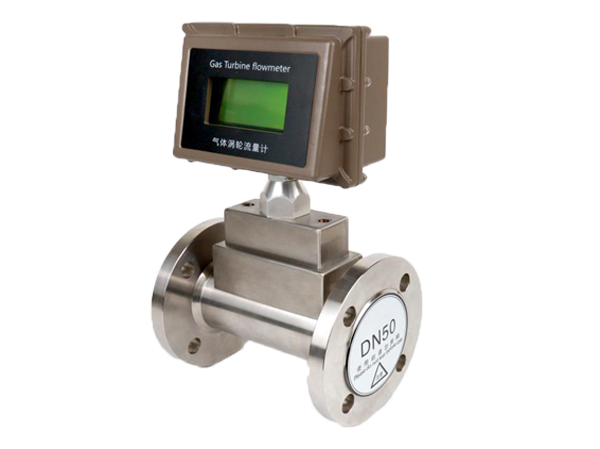
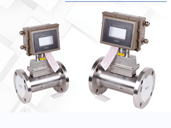
Manufacturer of gas turbine flowmeter
Nominal diameter: DN50-DN400
Function application: mainly used for trade settlement, mobile prepaid system, remote meter reading
Advantages and features: low initial flow rate, good repeatability, and low pressure loss
Applicable media: natural gas, compressed air, nitrogen, etc
Gas turbine flow meters are mainly used for measuring the flow rate of natural gas, air, nitrogen and other medium fluids in industrial pipelines. When measuring the volumetric flow rate under working conditions, they are almost unaffected by parameters such as fluid density, pressure, temperature, viscosity, etc.
Gas turbine flowmeter is a precision measuring instrument used for gas flow measurement. This product is carefully developed by our company in combination with our own products. It has the characteristics of low pressure loss, high accuracy, low starting flow rate, good anti vibration and anti pulsating flow performance, and wide range ratio. Make the flowmeter a commercial trade measuring instrument that can accurately measure the cumulative amount of gas.
When the airflow enters the flowmeter, it is first accelerated by a specially structured leading fluid. Under the action of fluid, due to the angle between the turbine blades and the fluid flow direction, the turbine generates rotational torque, which begins to rotate after overcoming the resistance torque and friction torque. When the torque reaches equilibrium and the speed remains constant, the angular velocity of the turbine rotation is linearly related to the flow rate. By utilizing the principle of electromagnetic induction, a rotating turbine drives the top magnetic field of the signal generator to periodically change its magnetic resistance, causing a corresponding change in the magnetic field. As a result, pulse signals proportional to the fluid volume flow rate are induced at both ends of the coil. The signal is amplified by a preamplifier, shaped, and input into the flow integrator for calculation and processing along with the pressure and temperature signals detected by the pressure sensor and temperature sensor, directly displaying the standard instantaneous volume flow rate and total volume.
This series of flow meters considers the compressibility of gases, and the volume is closely related to the temperature and pressure of the medium. Therefore, temperature and pressure sensors are added to track the temperature and pressure changes of the medium, directly converting the operating flow rate into the standard flow rate, ensuring the accuracy of measurement. Gas turbine flow meters can be widely used in gas metering and gas pressure regulating stations for petroleum, chemical, power, industrial boilers, natural gas transmission and distribution networks, urban natural gas metering, and other fields.
Advantages and characteristics of gas turbine flowmeter:
- High quality aluminum alloy turbine with higher stability and corrosion resistance;
- Specialized instrument bearings have low friction resistance, good sealing performance, and long service life;
- The isolation between the measuring room and the ventilation room ensures the safety of the instruments;
- The intelligent flowmeter integrates a microprocessor, temperature, and pressure sensors to directly measure the flow rate, temperature, and pressure of the measured gas, and automatically performs flow tracking compensation and compression factor correction calculations. It displays the accumulated gas volume under standard conditions (Pb=101.325KPa, Tb=293.15K) and can query temperature and pressure values in real time;
- Wide flow range (Qmax/Qmin ≥ 20:1), good repeatability, high accuracy (up to 1.0 level), low pressure loss, low starting flow rate, up to 0.6m3/h;
- The instrument has pulse signal and analog signal output, as well as RS485 communication interface. It adopts a dedicated MODEM and can be directly connected to the customer’s remote reading system through the telephone network to achieve centralized data collection and real-time management of computer data;
- Intelligent instrument coefficient multi-point nonlinear correction;
- Built in pressure and temperature sensors, high safety performance, compact structure, and beautiful appearance;
- Dedicated LCD display screen, intuitive and convenient reading. Intelligent flow meters can simultaneously display cumulative flow rate under standard conditions, instantaneous flow rate under standard conditions, as well as parameters such as temperature and pressure of the medium;
- The system operates with low power consumption and can be powered by lithium batteries or an external power source;
- Can be used in conjunction with IC card prepaid system for easy trade settlement.
Technical parameters of gas turbine flowmeter:
| property | Technical parameter |
| Instrument caliber and connection mode | 25, 40, 50, 80, 100, 150, 200, 250 adopts flange connection; |
| accuracy level | ±1%R |
| Range ratio | 1:10、1:20、1:30 |
| Display mode | The widescreen display simultaneously displays instantaneous flow, daily cumulative flow, total cumulative flow temperature, pressure, time, date, and battery level |
| Instrument material | Body: 304 stainless steel, cast aluminum material; Impeller: anti-corrosion ABS or high quality aluminum alloy; Display: cast aluminum; |
| Medium temperature | -10℃~+100℃ |
| Environmental condition | Medium temperature: -10℃ ~ +100℃, relative humidity 5% ~ 90%, atmospheric pressure 86 ~ 106Kpa |
| Communication signal | Three-wire pulse, three-wire 4-20mA, RS485 protocol, IC card signal |
| Power supply | Built-in lithium battery, external 24VDC dual power supply |
| Transmission distance | ≤1000m |
| Class of protection | IP65 |
Correct selection of gas turbine flowmeter
- Accuracy level: Generally speaking, the selection of turbine flow meters is mainly based on their high accuracy. However, the higher the accuracy of the flow meter, the more sensitive it is to changes in on-site usage conditions. Therefore, the choice of instrument accuracy should be carefully considered from an economic perspective. For trade settlement instruments for large-diameter gas pipelines, it is cost-effective to invest more in instruments, while for situations with small transport volumes, a medium precision level can be selected.
- Flow range: as described above
- Gas density: The main influence of fluid properties on gas turbine flow meters is gas density, which has a significant impact on instrument coefficients and mainly occurs in low flow areas. If the gas density changes frequently, corrective measures should be taken for the flow coefficient of the flowmeter.
- Pressure loss: Try to choose turbine flow meters with low pressure loss. The smaller the pressure loss of the fluid passing through the turbine flowmeter, the less energy is consumed by the fluid from the input to the output pipeline, which reduces the total power required. This can greatly save energy, reduce transportation costs, and improve utilization efficiency.
- Structural type:
(1) The internal structure should use a reverse thrust turbine flowmeter. Because the reverse thrust structure can keep the impeller in a floating state within a certain flow range, there are no contact points in the axial direction, and there is no end face friction and wear, which can extend the service life of the bearing.
(2) According to the selection of pipeline connection methods, flow meters can be installed horizontally and vertically. Horizontal installation and pipeline connection methods include flange connection, threaded connection, and clamp connection. Select flange connection for medium caliber; Use threaded connections for small-diameter and high-pressure pipelines; Clamp on connections are only suitable for low-pressure small and medium-sized pipe diameters; Vertical installation only has threaded connections.
(3) Select based on environmental conditions, taking into account the effects of temperature and humidity. Natural gas metering should choose intrinsically safe explosion-proof turbine flow meters.
- Bearings: The bearings of turbine flow meters are generally made of three types of materials: tungsten carbide, polytetrafluoroethylene, and carbon graphite. The bearings of natural gas measuring instruments should be made of tungsten carbide material.
The above are the main aspects to consider when selecting. Due to the wide variety of types and specifications of turbine flow meters, especially the differences in product quality among different manufacturers, when selecting, it is necessary to collect relevant technical standards and other information from manufacturers and products as much as possible, conduct repeated investigations and comparisons, and then decide whether to choose.
Precautions for installation of gas turbine flowmeter:
Before installation, the pipeline must be blown clean to prevent residual iron filings from affecting the normal operation of the flowmeter.
Before installation, if the turbine can rotate flexibly without irregular noise when blown by a small airflow, and the ink injection display is normal, then the flowmeter can be installed and used.
When installing the flowmeter, a sealing gasket should be added in the middle of the flange of the pipeline.
A filter should be installed in front of the flowmeter, and an oil filter should be installed in areas with dirty air. Before placing an order, users can also place an order with our company. It is strictly prohibited to directly connect the filter and flowmeter.
The flowmeter should be equipped with shut-off valves before and after installation.
There should be no protrusions on the inner diameter of the pipeline at the flange connection.
When installing the flowmeter, it is strictly prohibited to directly weld at its inlet and outlet flanges to avoid burning out the internal parts of the flowmeter.
The flowmeter should be installed in a location that is easy to maintain, free from strong electromagnetic interference, mechanical vibration, and thermal radiation.
Flow meters should not be used in situations where flow is frequently interrupted and there is strong pulsating flow or pressure pulsation.
When installing the flowmeter outdoors, there should be a cover on the upper part to prevent rainwater from entering and direct sunlight from affecting the service life of the flowmeter.
The flow meter can be installed horizontally or vertically, and the direction of fluid flow should be consistent with the direction marked on the housing. A straight pipe section of not less than 10Dn should be ensured upstream of the flow meter, and a straight pipe section of not less than 5Dn should be ensured behind the meter.
In order not to affect the normal transportation of fluid, it is recommended to install a bypass pipeline according to Figure 2, and the bypass pipeline valve must be closed during normal use.
During pipeline construction, consideration should be given to installing expansion pipes or corrugated pipes to avoid serious stretching or breakage of flow meters;
It should be ensured that the connection between the pipeline and the inlet and outlet of the flowmeter is coaxial, and the gasket and weld should be prevented from protruding into the pipeline, otherwise it will disturb the flow profile.
When using an external power source, the flowmeter must have a reliable grounding, but it must not share the ground wire with the high-voltage system. During pipeline installation or maintenance, the ground wire of the welding system must not be overlapped with the flowmeter.
When conducting a sealing pressure test after pipeline installation, attention should be paid to the higher pressure that the flow meter pressure sensor can withstand (i.e., the higher pressure of the medium on the identification certificate) to avoid damaging the pressure sensor.