Insert type vortex flowmeter is an instrument used in industries such as petroleum. This instrument has excellent anti vibration performance, no zero drift, and high reliability. Through extensive waveform and frequency analysis of the vortex flowmeter over a long period of time, the optimal probe shape, wall thickness, height, probe rod diameter, and matching piezoelectric crystal are designed. Advanced CNC lathes are used for processing to ensure the technical parameters of coaxiality and smoothness, and special process processing is carried out to overcome the common problem of the inherent self oscillation frequency of the vortex flowmeter affecting the signal to the greatest extent possible.
Manufacturer of insert type vortex flowmeter
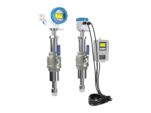
The insert type vortex flowmeter mainly consists of three parts: pressure sensor, measurement circuit, and process connector. It can convert the physical pressure parameters of gases, liquids, etc. sensed by pressure sensors into standard electrical signals, which are supplied to secondary instruments such as indicator alarms, recorders, and regulators for measurement, indication, and process adjustment. The insert type vortex flowmeter currently used in small-scale automation control is generally based on the piezoresistive principle, which means that the resistance of the varistor changes when it is compressed, amplified by an amplifier, and calibrated with standard pressure to perform pressure detection.
Technical parameters of insert type vortex flowmeter
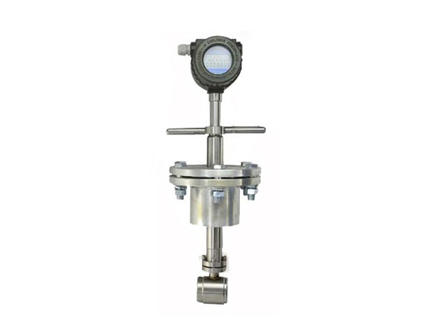
◆ Connection methods: flange card type, flange type, plug-in type
Measurement medium: gas, liquid, vapor
The caliber specification for flange card mounted calibers is 25, 32, 50, 80, and 100.
◆ Flange connection type with a diameter selection of 100, 150, 200
◆ Flow measurement range Normal measurement flow velocity range Reynolds number 1.5 × 10⁴~4 × 10⁶; Gas velocity of 5-50m/s; The normal measurement flow range for liquid is 0.5-7m/s. The measurement ranges for liquid and gas flow are shown in Table 2; The steam flow range is shown in Table 3
Measurement accuracy: Level 1.0, Level 1.5, Level 2.5
◆ Temperature of the tested medium: normal temperature -25 ℃~100 ℃
◆ High temperature -25 ℃~150 ℃ -25 ℃~250 ℃
Output signal pulse voltage output signal high level 8-10V low level 0.7-1.3V
◆ Pulse duty cycle of about 50%, transmission distance of 100m ◆ Pulse current remote transmission signal of 4-20mA, transmission distance of 1000m
◆ Instrument operating environment temperature: -25 ℃~+55 ℃ humidity: 5-90% RH50 ℃
◆ Material: Stainless steel, aluminum alloy
◆ Power supply DC24V or lithium battery 3.6V
◆ Explosion proof level, intrinsic safety type iaIIbT3-T6, protection level IP65, intelligent vortex flowmeter. Product selection code: Flow rate range ㎡/h LU-25 DN25 1~10 (liquid) 25~60 (gas) LU-32 DN32 1.5~18 (liquid) 15~150 (gas) LU-40 DN40 2.2~27 (liquid) 22.6~150 (gas) LU-50 DN50 4~55 (liquid) 35~350 (gas) LU-80 DN80 9~135 (liquid) 90~900 (gas) LU-100 DN100 14~200 (liquid) 140~1400 (gas) LU-150 DN150 32~480 (liquid) 300~3000 (gas) LU-200 DN200 56~800 (gas) Liquid 550~5500 (gas)
Measurement range of insert type vortex flowmeter
Liquid – maximum flow rate according to pipeline diameter, refer to Table 1 or Table 2. The minimum flow rate is generally referred to in Table 1 based on its density (g/) and diameter. When the liquid viscosity is greater than 1 × (or 1cst), it is referred to in Table 2 based on viscosity and diameter. If the viscosity of the liquid is 6 times, it cannot be measured. If two different values are found for the same liquid based on its density and viscosity, the higher value should be taken as the lower limit of flow rate.
Advantages of insert type vortex flowmeter
- The sensor of the intelligent vortex flowmeter has strong universality, which makes the sensor have good interchangeability. Advanced CNC equipment is used to process the sensor body and vortex generator to ensure processing accuracy, thereby making the components (especially the vortex generator) highly versatile, and truly ensuring that the repeatability and accuracy of the sensor will not be affected by the replacement of components; Capable of generating strong and stable vortex signals.
- The structure is simple and sturdy, with no movable parts, high reliability, and easy to use and maintain.
- The detection element does not come into contact with the medium, with stable performance and long service life. The sensor is installed separately from the vortex generator using a detection probe, and a high-temperature resistant piezoelectric crystal is sealed inside the detection probe, which does not come into contact with the measured medium. Therefore, the vortex flowmeter has the characteristics of simple structure, good versatility, and high stability.
- Output pulse signals or analog signals proportional to the flow rate, with no zero drift, high accuracy, and convenient networking with computers
- Wide measurement range, with a range ratio of up to 1:10
When measuring volumetric flow rate with a vortex flowmeter, no compensation is required. The signal output by the vortex flowmeter is actually linearly related to the flow rate, that is, directly proportional to the volumetric flow rate. The purpose of pressure and temperature compensation is to obtain the density of the fluid, which is multiplied by the volumetric flow rate to obtain the mass flow rate. If measuring the volumetric flow rate of a gas, compensation is not required. - Low pressure loss.
Using a DN50 vortex flowmeter to measure the flow rate of combustible gases, if the maximum flow rate Qmax in the pipeline is 200m3/h, the pressure loss of the sensor is Δ P=1.08 × 10⁻⁶. Within a certain Reynolds number range, the flow characteristics are not affected by fluid pressure, temperature, viscosity, density, or composition, but only by the shape and size of the vortex generator. - It has a wide range of applications and can measure the flow rates of steam, gas, and liquid.
Precautions for installation of plug-in vortex flowmeter
1: Avoid strong vibration and strong magnetic interference: Pipeline vibration caused by pumps or valves can cause measurement errors, and in severe cases, even affect the normal measurement of instruments. Therefore, pipeline fastening devices must be added at 2D upstream and downstream locations to support pipelines or isolate them with hoses to enhance seismic resistance.
2: Avoid direct effects of high temperature heat sources and radiation sources. If installation is necessary on site, insulation and ventilation measures must be taken. When measuring high-temperature media such as steam, insulation treatment should be carried out to prevent the converter temperature from being too high, to ensure that the flowmeter housing is exposed for heat radiation and to prevent the instrument electronic components from overheating and affecting the lifespan of the flowmeter.
3: Avoid high temperature environments and highly corrosive gas environments. Of course, if installation is necessary, ventilation measures must be added.
4: Explosion proof sensors and transmitters are installed in hazardous areas, and related equipment such as safety barriers, display instruments, power supplies, computers, etc. must be installed in a safe environment. Sensors and transmitters should be reliably grounded, and explosion-proof grounding wires should not be shared with the protective grounding of strong electrical systems.
5: Try to avoid installing flow meters on long overhead pipelines, as the sagging of the pipeline can easily cause seal leakage between the flow meter and the flange. The necessary installation conditions require pipeline support points to be set up at 2D positions upstream and downstream of the flow meter on site.
6: It is best to install the instrument indoors. When installing outdoors, attention should be paid to waterproofing, moisture resistance, and sun protection. Protective covers should be used. Special attention should be paid to bending the cable into a U-shape at the electrical interface to prevent water from entering the amplifier housing along the cable.
7: Flow meters should be avoided from being installed near the valve outlet, otherwise the opening and closing of the valve will affect the service life of the flow meter. In severe cases, it can damage the flow meter. For the convenience of maintenance, a bypass pipeline should be installed, especially in situations where fluid cannot be stopped in the middle of the production process.
8: It should be ensured that the medium inside the pipeline is in a full state. The flowmeter can be installed on a horizontal or vertical pipeline. If installed on a vertical pipeline, the measured medium must flow from bottom to top when it is a liquid.
9: A flow control valve should not be installed upstream of the flowmeter, but should be placed downstream of the flowmeter.