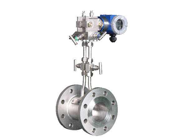
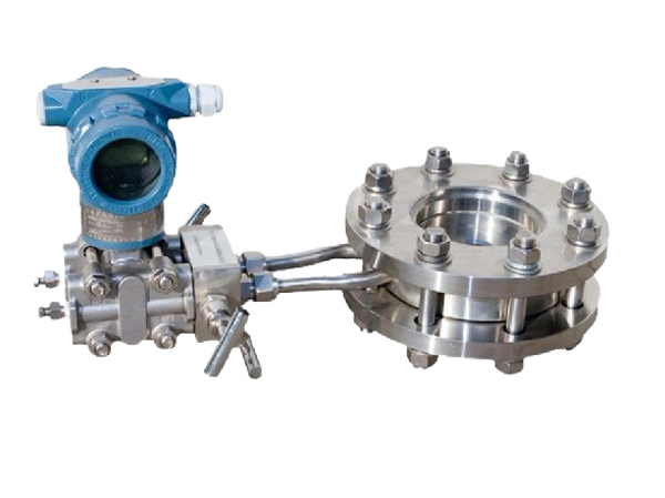
Orifice plate flowmeter/differential pressure flowmeter is a high range ratio differential pressure flow device composed of a standard orifice plate and a multi parameter differential pressure transmitter (or differential pressure transmitter, temperature transmitter, and pressure transmitter), which can measure the flow of gas, steam, liquid, and natural gas. It is widely used in process control and measurement in the fields of petroleum, chemical, metallurgy, power, heating, water supply, etc.
Manufacturer of intelligent gas orifice flowmeter
● Range accuracy: 1% ● Repeatability: 0.1%
● Range ratio: 10:1 ● High static pressure: 40MPA
● nominal diameter: DN15-DN1200 ● connection method: flange connection
● Working temperature:- 50~550 ℃ ● Voltage resistance: 10MPa
● Display: Flow/Pressure/Temperature ● Type: Differential Pressure Type
Applicable media: gases, steam, liquids, and natural gas.
Application scenarios: Process control and measurement in the fields of petroleum, chemical, metallurgy, electricity, heating, water supply, etc.
Product Features
Negligible effects of temperature and static pressure
Continuous work for 5 years without calibration required
The standard throttling device does not require real flow calibration and can be put into use.
Widely applicable, all single-phase flows can be measured, and some mixed phase flows can also be applied.
The structure of the throttling device is easy to replicate, simple and sturdy, with stable and reliable performance, long service life, and low price.
Product application
Orifice flowmeter is a high range ratio differential pressure flow device composed of a standard orifice plate and a multi parameter differential pressure transmitter (or differential pressure transmitter, temperature transmitter, and pressure transmitter). It can measure the flow of gas, steam, liquid, and natural gas, and is widely used in process control and measurement in fields such as petroleum, chemical, metallurgy, power, heating, and water supply.
product mix
Composition of throttling device
- Throttling components: standard orifice plate, standard nozzle, long diameter nozzle, 1/4 circular orifice plate, double orifice plate, eccentric orifice plate, circular orifice plate, conical inlet orifice plate, etc
- Pressure collection device: ring chamber, pressure collection flange, clamping ring, pressure pipe, etc
- Connecting flanges (flanges according to national standards, various standards, and other design departments) and fasteners.
- Measuring tube
Installation method of orifice flowmeter/differential pressure flowmeter
Installation pipeline conditions for orifice flowmeter:
(1) The straight pipe section before and after the throttling element must be straight and there must be no visible bending.
(2) The straight pipe section used for installing throttling components should be smooth. If it is not smooth, the flow coefficient should be multiplied by the roughness to correct for sparsity.
(3) To ensure that the fluid flow forms a fully developed turbulent velocity distribution 1D in front of the throttling element, and to make this distribution uniformly axisymmetric
(1) The straight pipe section must be circular, and the roundness requirements for the 2D range of the throttling element are very strict, with certain roundness indicators. Specific measurement method:
(A) Measure the inner diameters of at least four pipes on four vertical pipe sections, OD, D/2, D, and 2D, at equal angular distances in front of the throttling element, and take the average value D. The difference between the single measurement value and the average value of any inner diameter shall not exceed ± 0.3%
(B) After the throttle element, measure 8 single inner diameter values using the above method at the OD and 2D positions. The maximum deviation between any single measurement value and D should not exceed ± 2%
(2) A sufficiently long straight pipe section is required before and after the throttling element, which is related to the form of the local resistance element in front of the throttling element and the diameter ratio β.
(4) The length of the straight pipe section between the first and second resistance elements on the upstream side of the throttling element can be taken as half of the listed value in the form of the second resistance element and β=0.7 (regardless of the actual β value)
(5) When the upstream side of the throttling element is an open space or a large container with a diameter ≥ 2D, the length of the straight pipe between the open space or large container and the throttling element shall not be less than 30D (15D). If there are other local resistance components between the throttling element and the open space or large container, in addition to the minimum straight pipe length 1 specified for attachment between the throttling element and the local resistance component, the total length of the straight pipe section from the open space to the throttling element shall not be less than 30D (15D).