Liquid gear flowmeter is a type of volumetric flowmeter used for precise continuous or intermittent measurement of liquid flow rate or instantaneous flow rate in pipelines. It is particularly suitable for flow measurement of high viscosity media such as heavy oil, petroleum, polyvinyl alcohol, chemical, metallurgical, resin, etc.
Manufacturer of intelligent liquid oval gear flowmeter
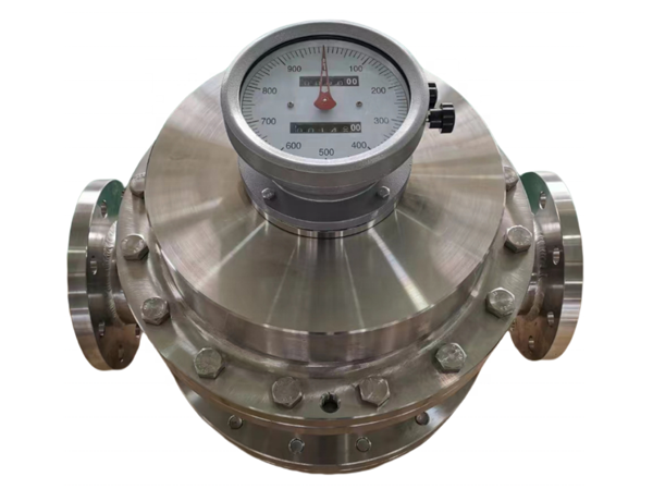
The display of the flow signal of the gear flowmeter has two types: local display and remote transmission display. After a series of deceleration and speed ratio adjustment mechanisms, the rotation of the gears is directly connected to the indicator pin on the instrument panel and the total amount is displayed through a mechanical counter; Remote transmission display mainly drives the permanent magnet to rotate through the gear after deceleration, so that the contacts of the spring relay close or open synchronously with the rotation frequency of the permanent magnet, thereby emitting a series of electrical pulses to be transmitted remotely to another display instrument.
Flow characteristics of gear flowmeter
- Flow measurement is independent of the flow state of the fluid, as the elliptical gear flowmeter relies on the pressure head of the measured medium to drive the elliptical gear to rotate for measurement.
- The higher the viscosity of the medium, the smaller the amount of leakage from the gear and measuring space gap. Therefore, the larger the viscosity of the measured medium, the smaller the leakage error, and the more advantageous it is for measurement.
- Gear flowmeter has high measurement accuracy and is suitable for measuring the flow rate of high viscosity media, but it is not suitable for fluids containing solid particles (solid particles can jam the gear, making it impossible to measure the flow rate). If gas is mixed in the measured liquid medium, it can also cause measurement errors.
Gear type flowmeter installation
- Installation site
Flowmeter installation should choose the right place, pay attention to the following points.
(1) The surrounding temperature and humidity should meet the requirements of the manufacturer, the general temperature is -10(-15) ~ 40(50)℃, and the humidity is 10% ~ 90%.
(2) Direct sunlight in the summer will increase the temperature, close to the place of radiant heat. It will also increase the temperature, and such places should take shading or insulation measures.
(3) Non-dust-proof and water-resistant instruments should avoid corrosive atmospheres or wet places, because parts such as the integrator reduction gear will be damaged by corrosive gases and day-night temperature condensation. If it cannot be avoided, the internal cavity can be blown with clean air to maintain a small positive pressure.
(4) Avoid vibration and shock places.
(5) There should be enough space for easy installation and daily maintenance.
2, instrument posture, flow direction, and pipe connection
The installation position must be horizontal and vertical, so that the rotor shaft is parallel to the ground (except for the design of the vertical structure rotor shaft), and other models are generally installed horizontally according to the requirements of the operating instructions. Vertical installation To prevent dirt and debris from falling into the flow meter from above the pipe, install it in the bypass pipe.
The actual flow direction should be consistent with the direction indicated by the instrument housing. Positive displacement flowmeters can generally only be measured in a single direction, and if necessary, check valves are installed downstream to avoid damage to the instrument.
To make the flowmeter not withstand pipeline expansion, contraction, deformation and vibration; Prevent the system from vibration due to unreasonable valve and pipeline design, especially to avoid resonance. Do not allow the instrument to be stressed during installation, such as the upper and lower pipe flanges are not parallel, the distance between the flanges is too large, and the pipe has different cores and other bad pipe layout is unreasonable installation. Especially for the flow meter with no separation measuring chamber, the pressure shell and the measuring chamber should be paid more attention, because the larger installation stress will cause deformation, affect the measurement accuracy, and even jam the moving measuring element. - Prevent foreign phase fluid from entering the instrument
The gap between the measuring chamber of the gear flowmeter and the moving detection part is very small, and the particle impurities in the fluid affect the normal operation of the instrument, resulting in stuck or premature wear. A filter must be installed upstream of the meter. And regular cleaning; When measuring gas, consider adding protective equipment such as a sediment sink or water absorber. Gas must be avoided from entering the piping system and a gas separator should be set up if necessary.
4, reduce the harm of pulsating flow, impact flow or overload flow
Although there are some examples of successful use in the suction end of the pump, the meter should be installed in the outlet end of the pump. Pulsating and impinging flows can damage flowmeters. The ideal flow source is a centrifugal pump or high tank. If it is necessary to use a reciprocating pump, or where the pipeline is prone to overload impact, or water hammer impact and other impact currents, protective equipment such as buffer tanks, expansion chambers or safety valves should be installed. Flowmeter overload and overspeed operation may bring irreparable danger! If there is a possibility of excessive overload flow in the pipe system, protection facilities such as flow limiting orifice plates, constant flow valves or flow controllers should be installed downstream.
5, uninterrupted installation
Due to the defect of pipeline interruption caused by the damage of the measuring element of the gear flowmeter, the parallel system redundancy of automatic switching equipment should be equipped in the place of continuous production or no interruption. It can also take the parallel operation mode that the flow is commonly used, and the other one can still circulate if the fault occurs.