Liquid ultrasonic flowmeter refers to a flowmeter developed based on the principle that the propagation speed of ultrasonic waves in a flowing medium is equal to the vector sum of the average flow velocity of the measured medium and the speed of the sound waves in a stationary medium. It mainly consists of transducers and converters, and includes different types such as Doppler method, velocity difference method, beam offset method, noise method, and correlation method

Manufacturer of intelligent liquid ultrasonic flowmeter
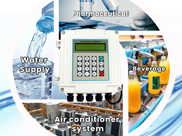
Various ultrasonic flow meters have been widely used in industrial production, commercial measurement, and water conservancy testing, such as:
In the measurement of raw water, tap water, reclaimed water, and sewage in the municipal industry, ultrasonic flow meters have the characteristics of large range ratio and no pressure loss, which improves the water transmission efficiency of the pipeline network while ensuring measurement accuracy;
In the flow measurement of water pipelines, channels, pump stations, and power stations in the water conservancy and hydropower industry, ultrasonic flow meters have the characteristics of large diameter, on-site installation, and online calibration, making accurate measurement possible. Simultaneously achieving equipment optimization and economic operation through metering of individual pumps and turbines;
In the measurement of industrial cooling circulating water, ultrasonic flow meters have achieved online continuous flow with pressure installation and online calibration;
Multi channel ultrasonic flow meters have achieved an accuracy (indication error) of over 0.2% in commercial metrology.
(1) The propagation time method is applied to clean, single-phase liquids and gases. Typical applications include factory discharge liquids, strange liquids, liquefied natural gas, etc;
(2) There is already good experience in the application of gas in the field of high-pressure natural gas;
(3) The Doppler method is suitable for two-phase fluids with relatively low heterogeneous content, such as untreated wastewater, factory discharge fluids, and dirty process fluids; Usually not suitable for very clean liquids.
Characteristics of liquid ultrasonic flowmeter
(1) Ultrasonic flow meters can be used for non-contact measurement. The clamp type transducer ultrasonic flowmeter does not require the installation of a stop flow pipe, as long as the transducer is installed outside the existing pipeline. This is a unique advantage of ultrasonic flow meters in industrial flow meters, making them suitable for mobile (i.e. non fixed installation) measurement and assessment of flow conditions in pipelines.
(2) Ultrasonic flowmeter is used for flow unobstructed measurement without additional pressure loss.
(3) Ultrasonic flow meters are suitable for large circular and rectangular pipelines, and are not limited by pipe diameter in principle. They can be considered as the preferred choice when real flow verification cannot be achieved.
(4) Ultrasonic flow meters can measure non-conductive liquids and are a supplement to electromagnetic flow meters in unobstructed flow measurement.
(5) Some propagation time method ultrasonic flow meters are equipped with the function of measuring the propagation time of sound waves, which can measure the sound velocity of liquids to determine the type of liquid being measured. For example, when an oil tanker pumps oil ashore, it can be verified whether the measured oil is the oil or the bottom water of the tank.
(6) The propagation time method ultrasonic flowmeter can only be used for cleaning liquids and gases.
Working principle of liquid ultrasonic flowmeter
According to the principle of signal detection, ultrasonic flowmeters can be divided into propagation velocity difference method (direct time difference method, time difference method, phase difference method, and frequency difference method), beam offset method, Doppler method, cross-correlation method, spatial filtering method, and noise method.
- Time difference method: measure the time difference caused by different propagation speeds during forward and backward propagation to calculate the velocity of the measured fluid.
It uses two acoustic transmitters (SA and SB) and two acoustic receivers
(RA and RB). Two sets of sound waves from the same source are transmitted separately between SA and RA, and between SB and RB. They are installed along the pipeline at a θ angle (generally θ=45 °) with the pipeline (as shown in Figure 1). Due to the acceleration of sound waves downstream by the fluid and the delay of sound waves upstream, the time difference between them is proportional to the flow velocity. It is also possible to measure the flow velocity by sending a sine signal to measure the phase shift between two sets of sound waves or by sending a frequency signal to measure the frequency difference. - Phase difference method: measures the calculation speed of phase difference caused by time difference during forward and backward propagation.
Its transmitter sends a beam of sound waves along an axis perpendicular to the pipeline, and due to the fluid flow, the sound wave beam is offset downstream by a certain distance. The offset distance is proportional to the flow velocity. - Frequency difference method: a method of measuring the frequency difference between forward and backward propagation.
When ultrasonic waves are transmitted in non-uniform fluids, scattering occurs. When there is relative motion between the fluid and the transmitter, a Doppler frequency shift occurs between the transmitted sound wave signal and the signal received after being scattered by the fluid. The Doppler shift is directly proportional to the fluid velocity. The area of the measured fluid in Figure 2-9 is located at the intersection of the transmitted beam and the received scattered beam. Require the beam to be very narrow, so that the angle θ between the two beams is not affected by the beam width. It is also possible to use only one converter as both a transmitter and a receiver, which is called single channel type.