oval gear flowmeter, also known as displacement flowmeter or gear flowmeter, is a type of volumetric flowmeter with high accuracy, especially suitable for measuring the flow rate of media with high viscosity.
Manufacturer of intelligent oval gear flowmeter
The oval gear flowmeter uses mechanical measuring elements to continuously divide the fluid into individual known volume parts, and measures the total volume of the fluid by sequentially and repeatedly filling and discharging these volume parts through the measuring chamber. It is a volumetric flowmeter used for precise continuous or intermittent measurement of liquid flow or instantaneous flow in pipelines. It is particularly suitable for flow measurement of high viscosity media such as heavy oil, polyvinyl alcohol, and resin. This type of flowmeter is mainly used in industrial and laboratory environments.
Working principle of oval gear flowmeter
The working principle of oval gear flowmeter is based on the rotational motion of gears in the medium. Specifically, when fluid flows through the instrument, the pressure difference generated at the inlet and outlet will drive a pair of interlocking oval gears to rotate. Every time the gear rotates, a certain amount of fluid is discharged. By measuring the rotational speed of the gear, the flow rate of the measured fluid can be calculated.
Basic structure of oval gear flowmeter
The oval gear flowmeter mainly consists of the following parts:
Measurement box: a container that holds fluids and serves as a measuring volume.
oval gear: A pair of interlocking oval gears used to divide fluids and drive rotation.
Upper and lower cover plates: form a sealed crescent shaped cavity (not absolutely sealed) with the measuring box and oval gear, serving as the unit for calculating primary displacement.
Sensor: Used to detect the rotational speed of oval gears and convert it into a flow rate value.
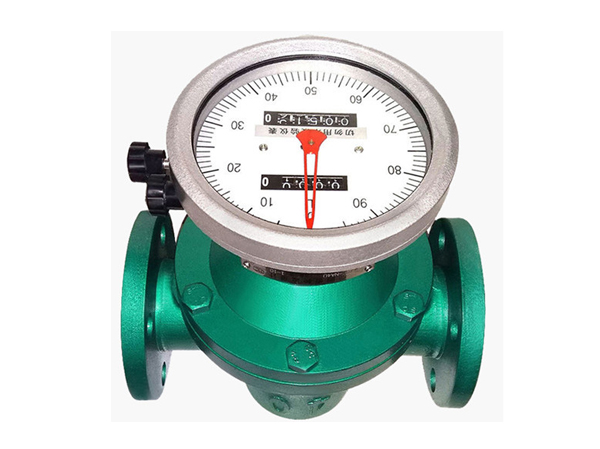
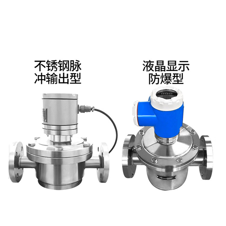
Display device: including two modes of local display and remote transmission display, used to display flow information.
oval gear flowmeter application guide
Flow measurement is independent of the flow state of the fluid, because the elliptic gear flowmeter relies on the inpressure of the measured medium to push the elliptic gear to rotate and measure. The larger the viscosity of the medium, the smaller the leakage from the gear and the measuring gap, so the larger the viscosity of the measured medium, the smaller the leakage error, the more favorable the measurement. The oval gear flowmeter has high measurement accuracy and is suitable for the measurement of flow in high viscosity media, but is not suitable for fluids containing solid particles (solid particles will jam the gear so that the flow cannot be measured). If there is gas in the measured liquid medium, it will also cause measurement errors. Install the elliptic gear flowmeter. Clean the pipe before installation. If the liquid contains solid particles, a filter must be installed upstream of the pipeline; If it contains gas, exhaust device should be installed. Elliptic gear flowmeter Elliptic gear flowmeter has no certain requirements for the front and rear straight pipe segments. It can be mounted horizontally or vertically. When installing, the elliptic gear axis of the flowmeter should be parallel to the ground.
Elliptic gear flowmeter use precautions
1) Cleaning the pipeline: the new pipeline should be cleaned before operation, and often then washed with real flow to remove residual welding chips and dirt. At this time, the front and rear stop valves of the instrument should be closed first, so that the liquid flow through the bypass pipe; If there is no bypass pipe, install a short pipe instead.
2) Exhaust gas: Usually after the solid liquid sweeps the line, there is still more air left in the pipeline. With the pressurized operation, the air flows through the positive displacement flowmeter at a higher flow rate, and the mobile measuring element may run too fast, damaging the shaft and bearing. Therefore, it is necessary to slowly increase the flow rate at the beginning, so that the air gradually overflows.
3) Bypass pipe switching sequence: When the liquid flow is transferred from the bypass pipe to the instrument, the opening and closing should be slow, especially on high temperature and high pressure pipelines. The first step is to slowly open the A valve, and the liquid first flows in the bypass pipe for a period of time; Step 2 Slowly open the B valve; Step 3 Slowly open the C valve; Step 4 Close valve A slowly. When closing, perform the operations in reverse order as described above. After starting, through the lowest pointer or word wheel and stopwatch, to confirm that there is no excessive flow, the best flow should be controlled at (70 ~ 80)% maximum flow to ensure the service life of the instrument.
4) Monitor the filter: the new line starts the filter network is most easily broken, and it is necessary to check whether the network is intact in time after the trial run. At the same time, when the filter is clean without dirt, the two parameters of pressure loss under the common flow rate are recorded, and it is not necessary to remove the check network blockage in the future, that is, to determine whether to clean according to the increase in pressure loss.
5) For the measurement of high-viscosity liquids: in high-viscosity liquids, generally heated to make it flow. When the meter is disabled, its internal liquid cools and thickens, and when it is activated, it must be heated until the liquid viscosity is reduced before the liquid flows through the meter, otherwise it will bite the active measuring element and damage the meter.
6) Lubricating oil: lubricating oil must be added before PDF is used for gas, and the level gauge of lubricating oil stock is often checked in daily operation.
7) Avoid sharp flow changes: Using gas waist wheel flow timing, it should be noted that there can be no sharp flow changes (such as the use of fast-opening valves), because of the inertia of the waist wheel, sharp flow changes will produce a large additional inertia force, so that the rotor is damaged. When used as the detection instrument of the control system, if the downstream control suddenly shuts off the flow, the rotor can not stop for a while, resulting in the compressor effect, the downstream pressure rises, and then the reverse flow, sending out the wrong signal.
8) The steam used in the flushing pipe is prohibited from passing through the oval gear flowmeter.
Application fields of oval gear flowmeter
Due to its high precision and strong viscosity adaptability, the oval gear flowmeter is widely used in the following fields:
Chemical industry: used to measure the flow rate of various chemical raw materials and products.
Petroleum: Measuring the flow rate of crude oil and refined oil during the extraction, processing, and transportation of petroleum.
Medicine: Measure the flow rate of various drugs and solvents during the pharmaceutical process.
Electricity: Measuring the flow of cooling water and fuel oil in electricity production.
Metallurgy: Measuring the flow rate of various metal liquids during the metallurgical process.
Food: Measure the flow rate of various food ingredients and products during food processing and packaging.