Gear flowmeter is a type of volumetric flowmeter used for precise continuous or intermittent measurement of liquid flow or instantaneous flow in pipelines. It is particularly suitable for flow measurement of high viscosity media such as heavy oil, polyvinyl alcohol, syrup, resin, etc.
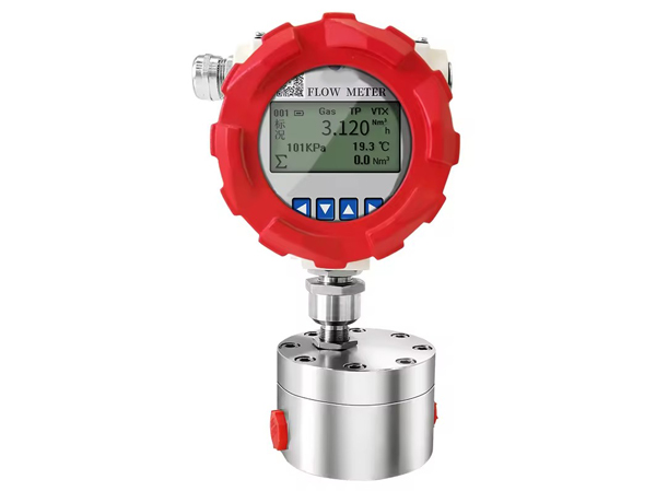
Manufacturer of mechanical gear flowmeter
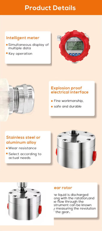
Characteristics of gear flowmeter
- Flow measurement is independent of the flow state of the fluid, as the elliptical gear flowmeter relies on the pressure head of the measured medium to drive the elliptical gear to rotate for measurement.
- The higher the viscosity of the medium, the smaller the amount of leakage from the gear and measuring space gap. Therefore, the larger the viscosity of the measured medium, the smaller the leakage error, and the more advantageous it is for measurement.
- Gear flowmeter has high measurement accuracy and is suitable for measuring the flow rate of high viscosity media, but it is not suitable for fluids containing solid particles (solid particles can jam the gear, making it impossible to measure the flow rate). If gas is mixed in the measured liquid medium, it can also cause measurement errors.
Principle of gear flowmeter
The display of the flow signal of the gear flowmeter has two types: local display and remote transmission display. After a series of deceleration and speed ratio adjustment mechanisms, the rotation of the gears is directly connected to the indicator pin on the instrument panel and the total amount is displayed through a mechanical counter; Remote transmission display mainly drives the permanent magnet to rotate through the gear after deceleration, so that the contacts of the spring relay close or open synchronously with the rotation frequency of the permanent magnet, thereby emitting a series of electrical pulses to be transmitted remotely to another display instrument.
Installation of gear flowmeter
- Installation site
The installation of flow meters should be carried out in a suitable location, and the following points should be noted.
(1) The surrounding temperature and humidity should comply with the manufacturer’s regulations, with a general temperature range of -10 (-15) to 40 (50) ℃ and humidity range of 10% to 90%.
(2) Direct sunlight in summer can cause temperatures to rise, approaching places with radiant heat. It can also raise the temperature, and shading or insulation measures should be taken in such places.
(3) Non dustproof and water-resistant instruments should avoid corrosive atmospheres or humid places, as components such as the accumulator, reduction gear, etc. can be damaged by corrosive gases and condensation caused by day night temperature differences. If unavoidable, clean air can be blown into the inner cavity to maintain a slight positive pressure.
(4) Avoid places with vibrations and impacts.
(5) There should be sufficient space for installation and daily maintenance. - Instrument posture, flow direction, and connection with pipelines
The installation posture must be horizontal and vertical, with the rotor axis parallel to the ground (except for vertical structure rotor axis design). Other models should be installed horizontally according to the requirements specified in the user manual. To prevent scale and debris from falling into the flowmeter from above the pipeline, it is installed vertically in the bypass pipe.
The actual flow direction should be consistent with the direction indicated on the instrument housing. Positive displacement flow meters can generally only be used for one-way measurement. If necessary, check valves should be installed downstream to avoid damaging the instrument.
To prevent the flowmeter from experiencing pipeline expansion, contraction, deformation, and vibration; Prevent vibration in the system due to unreasonable valve and pipeline design, especially avoiding resonance. During installation, do not subject the instrument to stress, such as when the flange planes of the upstream and downstream pipelines are not parallel, the distance between the flange faces is too large, or the pipelines are not concentric. Improper pipeline layout can lead to improper installation. Especially for flow meters without separate measuring chambers, where the pressure shell and measuring chamber are integrated, more attention should be paid, as high installation stress can cause deformation, affect measurement accuracy, and even cause jamming of movable measuring components. - Prevent out of phase fluids from entering the instrument
The gap between the measuring chamber of the gear flowmeter and the active detection component is very small, and the particle impurities in the fluid affect the normal operation of the instrument, causing jamming or premature wear. Filters must be installed upstream of the instrument. And regularly clean it; When measuring gases, it is necessary to consider installing protective equipment such as sediment collectors or water absorbers. Gas must be avoided from entering the pipeline system when measuring liquid pipelines, and gas separators should be installed if necessary. - Reduce the hazards of pulsating flow, shock flow, or overload flow
Although there are some successful examples of installation at the pump suction end, the instrument should be installed at the pump outlet end. Pulsating flow and shock flow can damage the flow meter. The ideal flow source is a centrifugal pump or a high-level tank. If it is necessary to use reciprocating pumps, or in places where pipelines are prone to overload impact or water hammer impact, protective equipment such as buffer tanks, expansion chambers, or safety valves should be installed. Overload and overspeed operation of flow meters may bring irreparable danger! If there is a possibility of excessive overload flow in the piping system, protective facilities such as flow limiting orifice plates, constant flow valves, or flow controllers should be installed downstream. - Continuous flow installation: Due to the disadvantage of pipeline interruption caused by damaged measuring components of gear flow meters, parallel system redundancy with automatic switching equipment should be equipped in places where continuous production or no interruption is allowed; It is also possible to adopt the commonly used parallel operation mode for flow, where one machine can still flow when it fails.