The flow meter is an instrument that indicates the measured flow rate and/or the total amount of fluid within a selected time interval. It is also an essential instrument for measuring liquid and gas flow rates. You must have seen many different types of flow meters in your daily life.
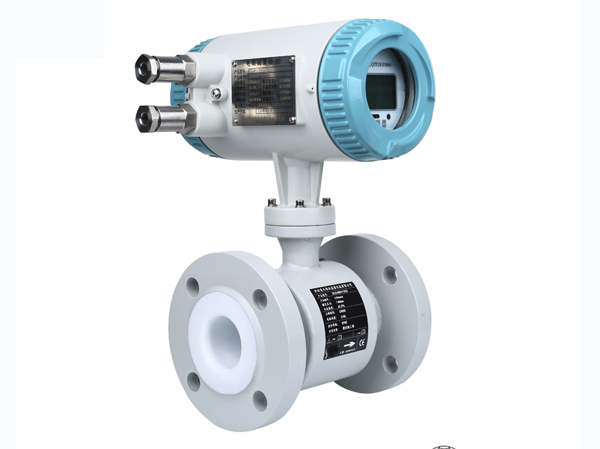
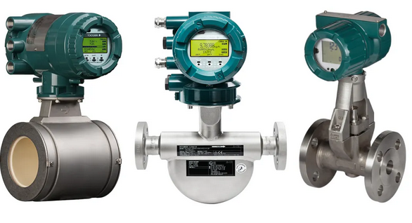
Introduction to the installation of electromagnetic flowmeter
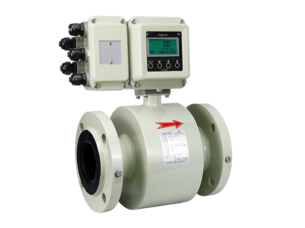
Introduction to the installation of electromagnetic flowmeter
The measurement principle of electromagnetic flowmeter does not depend on the characteristics of flow rate. If there is a certain turbulence and vortex generated in the non measurement area of the pipeline, it is irrelevant to the measurement.
A、 The installation site should not have large vibration sources and reinforcement measures should be taken to stabilize the pipelines near the instrument;
B、 Cannot be installed near large transformers, motors, pumps, and other equipment that generate large magnetic fields to avoid interference from electromagnetic fields;
C、 When connecting sensors to pipelines, full pipe operation should be ensured, and it is best to install them vertically;
D、 The transmitter housing can be grounded and connected to the nearest grounding grid; Shielded cable (split type) should be connected according to the instructions, and the signal cable (to the system) should be grounded at the single end of the shielding layer system; The short-circuit ring connecting the measurement sensor to the pipeline needs to be grounded, and the grounding resistance should be less than 10 ohms and cannot be shared with electrical grounding;
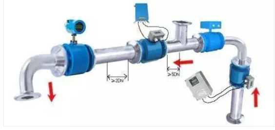
E、 There should also be a certain straight pipe section upstream of the flowmeter sensor, usually between 5D and 10D.
The installation details of electromagnetic flowmeter are as follows:
If there is a steady-state vortex in the measurement area, it will affect the stability and accuracy of the measurement. In this case, the length of the front and rear straight pipe sections can be increased, a flow stabilizer can be used, or the cross-section of the measurement point can be reduced to stabilize the flow velocity distribution.
The flowmeter can be installed horizontally and vertically, but it should be ensured to avoid the influence of sediment and bubbles on the measuring electrode, and the electrode axis should be kept horizontal. When installed vertically, the fluid should flow from bottom to top.
The sensor cannot be installed at the highest position of the pipeline, as this position is prone to the accumulation of air bubbles.
Ensure that the flow sensor is filled with the measured fluid in the pipeline during measurement and that there is no non full pipe state.
If the pipeline is not full or the outlet is empty, the sensor should be installed on a siphon tube.
The conventional straight pipe section requirement for electromagnetic flow meters is 10D in the front and 5D in the back, with different requirements for bent pipes and valves.
Reasons for grounding electromagnetic flowmeter:
The measuring electrode inside the electromagnetic flowmeter is in a direct current or alternating current electric field, and if its environment cannot be effectively shielded under interference free conditions, it can cause serious interference to the measurement.
The grounding of the sensor housing directly affects the accuracy and stability of the measurement. The grounding wire must not transmit any interference voltage. Therefore, electromagnetic flow meters require very reliable grounding and proper grounding shielding, otherwise interference currents will be generated.
The benefits of grounding electromagnetic flow meters:
If the pipeline connecting the flowmeter is insulated (relative to the measured medium), a grounding ring should be used, and its material should be selected according to the corrosiveness of the measured medium
If it is a PTFE lined measuring sensor, in order to ensure that the measuring sensor can work properly, a grounding ring should be selected.
Introduction to installation of ultrasonic flowmeter

Ultrasonic flowmeter is also a common flowmeter, and its installation is the simplest and most convenient among all flowmeters. Just select a suitable measurement point, input the pipeline parameters at the measurement point into the flowmeter, and then fix the probe on the pipeline.
Introduction to installation of vortex flowmeter
The main installation requirements for vortex flow meters are for the straight pipe section and pipeline vibration requirements. The upstream and downstream sides of the vortex flow sensor should have longer straight pipe sections; The pipeline must not have vibration. If there is vibration, fixed devices need to be added to both sides of the flowmeter.
Key points for installation of vortex flowmeter
For vortex flowmeters, when measuring gas flow, if the measured gas contains a small amount of liquid, the flowmeter should be installed at a higher point in the pipeline.
When measuring liquids, if the measured liquid contains a small amount of gas, the flow meter should be installed at a lower part of the pipeline.
Pressure and temperature measuring holes:
When pressure measurement is required, the pressure measuring hole must be set at a position 2-7D downstream of the flow meter. When temperature measurement is required, place the temperature sensor between 1-2D downstream from the pressure measuring point.
Pipeline support:
Try to install the flowmeter in a location where the vibration acceleration is less than 20m/s2. When the pipeline vibration is too strong, reinforcement and support should be installed on the pipeline.
Sealing gasket:
Never protrude the sealing gasket into the pipeline, otherwise it will cause unacceptable errors.
Introduction to installation of turbine flowmeter
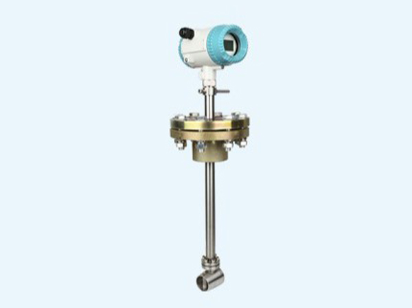
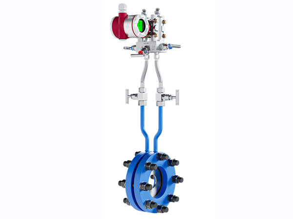
Introduction to the installation of Weiliba flowmeter
Introduction to the installation of Weiliba flowmeter
The Weiliba flow sensor is a flow sensor designed based on the differential pressure working principle and plug-in installation method. Structural features: Scientific cross-sectional shape, unique anti clogging design, sensor surface roughness treatment, and anti clogging groove.
Key points for installation of Weiliba flowmeter
Basic installation method for horizontal pipelines
For horizontal pipelines, it is recommended to install within a range of 160 degrees above the pipeline when measuring gas, especially for gases with a large amount of water powder. We only recommend this installation method;
When measuring liquids, it is recommended to install them within a range of 160 degrees below the pipeline, especially for liquids containing a large amount of gas. We only recommend this installation method;
But one thing to note is that for liquids that are highly prone to gasification, such as liquid olefin media, the insertion direction should be the same as the gas when installing, above the pipeline.
When measuring steam, it is recommended to install the sensor within 160 degrees below the pipeline and ensure that the sensor is at the highest point of the entire measuring device.
Basic installation method for vertical pipelines
For vertical pipelines, theoretically they can be installed within 360 degrees. For wet gases containing a large amount of moisture, it is recommended to tilt the sensor upwards by 5 degrees during installation.
For liquids containing a large amount of gas, it is recommended to tilt the sensor downwards by 5 degrees during installation, as shown in the figure on the right. For steam, it is recommended to tilt the sensor at 5 degrees when installing it, as shown in the figure on the right, and the sensor should be at the highest point in the entire measurement system.
The straight pipe section required for the installation of Weiliba
Minimum straight pipe section requirement -2D installation after bending as shown in the diagram.
When the straight sections upstream and downstream of the pipeline are not long enough, we recommend installing Velbar at twice the inner diameter of the pipeline after the bend, as the fluid profile after the bend is complex and the fluid coefficient K needs to be adjusted appropriately. After adjusting the K coefficient, the measurement accuracy is ± 3% and the repeatability is ± 0.3%
Introduction to installation of rotor flowmeter
Key points for installation of rotor flowmeter
- Instrument installation direction
The vast majority of rotor flow meters must be installed vertically on vibration free pipelines, without obvious tilting, and the fluid should flow through the instrument from bottom to top. The angle between the centerline of the rotor flowmeter and the plumb line is generally not more than 5 degrees, and for high-precision instruments (above level 1.5), the angle should be less than or equal to 20 degrees. If θ=12 °, an additional error of 1% will occur. There is no strict requirement for the length of the upstream straight pipe section of the instrument, but there are also manufacturers who require a length of (2-5) D, which is actually not very necessary. - Installation for dirty fluids
A filter should be installed upstream of the instrument. When a metal tube rotor flowmeter with magnetic coupling is used for fluids that may contain magnetic impurities, a magnetic filter should be installed in front of the instrument. Keep the float and cone tube clean, especially for small diameter instruments, as the cleanliness of the float significantly affects the measurement value. - Installation of rotor flowmeter for expanding range
If the required flow range for measurement is wide and exceeds 10, two floats of different shapes and weights can be placed in one instrument. When the flow is small, take the light float reading, and when the float reaches the top, take the heavy float reading. The range can be expanded to 50-100. - Installation of pulsating flow in rotor flowmeter
The pulsation of the flow itself, such as the presence of reciprocating pumps or regulating valves upstream of the proposed instrument location, or large load changes downstream, should be measured at a different location or remedied and improved in the pipeline system, such as installing buffer tanks; If there is oscillation in the instrument itself, such as low gas pressure during measurement, incomplete opening of the upstream valve of the instrument, or failure to install the regulating valve downstream of the instrument, targeted improvements should be made to overcome it, or instruments with damping devices should be selected instead. - The rotor flowmeter needs to exhaust the gas inside the instrument for liquid use
For angular metal rotor flow meters that are not in a straight line for import and export, when used for liquids, pay attention to whether there is residual air in the extended sleeve of the external float displacement, and it must be drained completely; If the liquid contains tiny bubbles that are prone to accumulate inside the casing during flow, it is even more important to exhaust them regularly. This is more important for small caliber instruments, otherwise it will significantly affect the flow indication. - The flow value of the rotor flowmeter should be converted as necessary
If the instrument is not specially customized to the rotor flowmeter manufacturer based on medium parameters such as density and viscosity, liquid instruments are usually calibrated with water for flow rate, and gas instruments are calibrated with air, with the calibration value in the engineering standard state. When the fluid density, gas pressure and temperature of the usage conditions are inconsistent with the calibration, necessary conversions should be made. The conversion formula and method are detailed in the manufacturer’s instruction manual for the rotor flowmeter.
Introduction to installation of orifice flowmeter
Installation requirements for orifice flowmeter
- Before installation, the orifice plate should be checked to ensure that the throttle device number and size meet the requirements of the pipeline installation position.
- When installing a new piping system, the installation of orifice plates must be carried out after flushing and sweeping the pipes.
- Pay attention to the installation direction of the orifice plate, where the “+” sign should face the flow beam.
- The center of the orifice plate should coincide with the centerline of the pipeline, and the concentricity error should not exceed a value of 0.015 (1/β -1).
- When installing the orifice plate in the pipeline, it should be ensured that its end face is perpendicular to the pipeline axis and the perpendicularity error should not exceed ± 1 °.
- The sealing gasket used for clamping the orifice plate (including between the ring chamber and the flange, and between the ring chamber and the orifice plate) shall not protrude into the inner wall of the pipeline after clamping.
- The installation of the orifice plate must be tight and no leakage is allowed. Therefore, installation work must be carried out before pipeline pressure testing.
- The pressure conduit should be laid vertically or obliquely, with an inclination of not less than 1:12. The inclination of fluids with higher viscosity should be increased. When the transmission distance of the differential pressure signal is greater than 3 meters, the pressure pipe should be inclined in sections, and gas collectors and settling devices should be installed at each high and low point respectively.
- In order to avoid distortion of differential pressure signal transmission, positive and negative pressure pipes should be laid as close as possible, and anti freezing measures should also be taken in cold areas. Electric heating or steam insulation can be used, but it is necessary to prevent the measured medium from overheating and vaporizing, and to prevent the generation of gas in the pressure tube, which may cause false differential pressure.
- When the orifice plate is installed on the vertical main pipeline, the position of the pressure tapping port can be arbitrarily selected on the plane of the pressure tapping device. The orifice plate is installed in a horizontal or inclined main pipeline, and the pressure port position is shown in Figure 4.
- The pressure tube is made of materials that are resistant to pressure and corrosion according to the properties of the measured medium. Its inner diameter should not be less than 6 millimeters and its length should be within 16 meters.
Introduction to Installation of mass flow meter
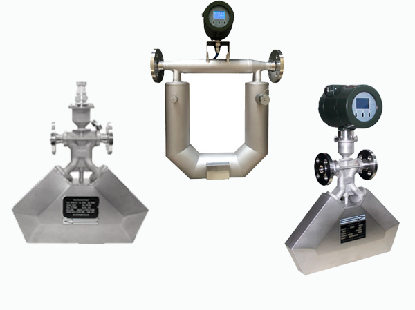
Installation requirements for quality flow meters
- The selection of installation location should avoid electromagnetic interference. The installation location of sensors and transmitters, as well as cable laying, should be as far away as possible from equipment that is prone to generating strong electromagnetic fields, such as high-power motors, transformer facilities, frequency conversion equipment, etc.
- The installation of mass flow sensors should ensure that the flow direction identification of the sensor is consistent with the fluid flow direction. And make the arrow point in the same direction as the flow configuration inside the transmitter. (Note: Mass flow meters can be used in both directions. If the installation direction is opposite to the actual flow direction, simply modify the flow configuration inside the transmitter.)
- Mass flow meters are flow meters measured based on the principle of measuring tube vibration. Therefore, when installing sensors, it is necessary to consider providing strong support near the flange of the process pipeline on both sides (about 2-10 times the diameter of the pipe) to avoid vibration of the instrument and related pipelines. If strong pipeline vibration is unavoidable, it is recommended to use flexible pipes to isolate the pipeline system from instrument sensors.
- Due to the fact that mass flow meters operate based on the Coriolis force principle, in order to avoid the influence of gravity on measurement accuracy. The measuring tube of the quality flowmeter should be installed vertically or horizontally with the ground plane as much as possible, whether upward or downward.
- During installation, the flange faces should be parallel to each other, and the centers of the two flanges should be located on the same axis to avoid additional stress. It is strictly prohibited to use sensors to straighten the upstream and downstream process pipelines, otherwise it will affect the measurement and even damage the sensors.
- It is recommended to install shut-off valves and bypasses on the upstream and downstream pipelines of the sensor to facilitate zero adjustment, daily maintenance, and ensure that the sensor can be in a full pipe state even when not in operation. The quality flow meter used in the trade handover site does not require a bypass. Use the regulating valve downstream of the flow meter for flow control.
- The installation direction of the sensor should ensure that the measured medium can completely fill the sensor. Do not collect gas for liquids. For gases, there should be no accumulation of liquid. For viscous, dirty, and high pour point media, they should be easy to drain (low point valves can also be installed on both sides as needed).
- Newly installed pipelines or pipelines that have not been used for a long time but have just been put into use must be purged of the entire pipeline (especially upstream pipelines) before installing the mass flow meter to ensure that there is no welding slag or debris left in the pipeline.
- It is recommended to add a filter at the inlet of the mass flow meter during installation. When measuring liquids, it is recommended to measure the tube vertically downwards
Through the introduction of the flow meters mentioned above, the installation methods of flow meters under common working conditions are already quite clear. For the installation of flow meters under complex working conditions, specific analysis is needed. Accumulating rich experience is the most important step in solving problems.