There are many types of flow meters based on their working principles, and when selecting, it is necessary to choose the appropriate flow meter according to the actual working conditions. Below, the editor has summarized the working principles of various flow meters, hoping to be helpful to everyone.
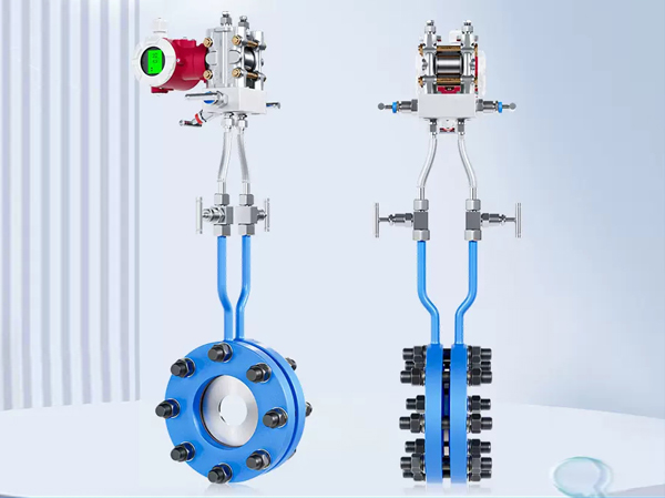
Differential pressure flowmeter
Differential pressure flowmeter is an instrument that calculates flow based on the differential pressure generated by the flow detection component installed in the pipeline, known fluid conditions, and the geometric dimensions of the detection component and pipeline. The differential pressure flowmeter consists of a primary device (detection component) and a secondary device (differential pressure conversion and flow display instrument). Differential pressure flow meters are usually classified in the form of detection components, such as orifice flow meters, Venturi flow meters, and averaging tube flow meters. The secondary device includes various mechanical, electronic, and electromechanical integrated differential pressure gauges, differential pressure transmitters, and flow display instruments. It has developed into a large category of instruments with a high degree of standardization (serialization, generalization, and normalization) and a wide range of types and specifications. It can measure both flow parameters and other parameters (such as pressure, level, density, etc.).
The detection components of differential pressure flow meters can be divided into several categories according to their operating principles: throttling device, hydraulic resistance type, centrifugal type, dynamic pressure head type, dynamic pressure head gain type, and jet type.
Differential pressure flowmeter is the most widely used type of flowmeter, with its usage ranking first among various flow meters. In recent years, due to the emergence of various new types of flow meters, their usage percentage has gradually decreased, but they are still the most important type of flow meter at present.
Target flowmeter
The target flowmeter was first applied in industrial flow measurement in the 1960s, mainly used to solve the flow measurement of high viscosity and low Reynolds number fluids. It has gone through two major development stages: pneumatic meters and electric meters. The SBL series intelligent target flowmeter is a new type of flow measurement instrument developed based on the measurement principle of the original strain gauge (capacitive) target flowmeter, using the latest force induction sensor as the measurement and sensitive transmission element, and utilizing modern digital intelligent processing technology.
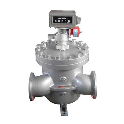
Positive displacement flowmeter
Positive displacement flowmeter, also known as fixed displacement flowmeter, abbreviated as PD flowmeter, is the most accurate type of flow meter. It uses mechanical measuring elements to continuously divide the fluid into individual known volume parts, and measures the total volume of the fluid based on the number of times the measuring chamber repeatedly fills and discharges that volume part of the fluid.
Volumetric flow meters can be classified according to their measuring components, including elliptical gear flow meters, scraper flow meters, dual rotor flow meters, rotary piston flow meters, reciprocating piston flow meters, disc flow meters, liquid sealed rotary cylinder flow meters, wet gas meters, and membrane gas meters.
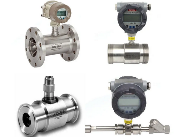
Turbine flowmeter
Turbine flowmeter is the main type of velocity flowmeter, which uses a multi blade rotor (turbine) to sense the average flow velocity of the fluid and derive the flow rate or total amount from it. Generally, it consists of two parts: sensors and displays, or it can be made as a whole.
Turbine flow meters, volumetric flow meters, and mass flow meters are known as the three types of flow meters with high repeatability and accuracy, and are one of the top ten types of flow meters.
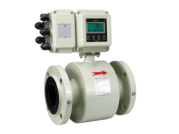
electromagnetic flowmeter
Electromagnetic flowmeter is an instrument made according to Faraday’s law of electromagnetic induction for measuring conductive liquids.
Electromagnetic flow meters have a series of excellent characteristics that can solve problems that are not easily applicable to other flow meters, such as measuring dirty and corrosive flows.
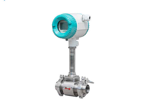
Vortex Flowmeter
A vortex flowmeter is an instrument that places a non streamlined vortex generator in a fluid, and the fluid alternately separates and releases two series of regularly arranged vortices on both sides of the generator. Vortex flowmeters can be classified according to frequency detection methods, including stress type, strain type, capacitance type, thermal sensitive type, vibration type, photoelectric type, and ultrasonic type.
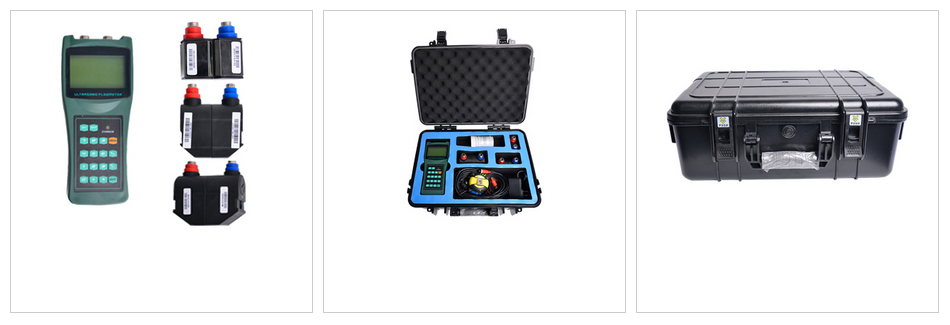
ultrasonic flowmeter
Ultrasonic flowmeter is an instrument that measures flow by detecting the effect of fluid flow on ultrasonic beams (or ultrasonic pulses). According to the principle of signal detection, ultrasonic flow meters can be divided into propagation velocity difference method (direct time difference method, time difference method, phase difference method, and frequency difference method), beam offset method, Doppler method, cross-correlation method, spatial filtering method, and noise method.
Ultrasonic flow meters, like electromagnetic flow meters, are unobstructed flow meters due to the absence of any obstruction in the instrument flow channel. They are a type of flow meter suitable for solving difficult flow measurement problems, especially in large-diameter flow measurement, and have outstanding advantages.
Coriolis mass flowmeter
The Coriolis mass flowmeter is a novel instrument for directly and accurately measuring fluid mass flow. The main structure adopts two parallel U-shaped tubes, and the bent parts of the two tubes vibrate slightly towards each other. The straight tubes on both sides will vibrate accordingly, that is, they will approach or open at the same time, that is, the vibration of the two tubes is synchronous and symmetrical. If fluid is introduced into the pipe while synchronously vibrating, causing it to flow forward along the pipe, the pipe will force the fluid to vibrate up and down together with it.
Thermal mass flowmeter
The thermal flowmeter sensor consists of two sensing elements, a speed sensor and a temperature sensor. They automatically compensate and correct for gas temperature changes. The electric heating part of the instrument heats the speed sensor to a constant value higher than the operating temperature, creating a constant temperature difference between the speed sensor and the sensor measuring the operating temperature. When the temperature difference remains constant, the energy consumed by electric heating, also known as the heat dissipation value, is directly proportional to the mass flow rate of the gas flowing through it.
Metal rotor flowmeter
The rotor flowmeter consists of two components, one of which is a conical tube that gradually expands from bottom to top; The other component of the rotor flowmeter is a rotor that is placed in a conical tube and can move freely along the centerline of the tube. When measuring the flow rate of a fluid with a rotor flowmeter, the measured fluid flows in from the lower end of the conical tube, and the flow of the fluid impacts the rotor, generating a force on it (the magnitude of this force varies with the flow rate); When the flow rate is large enough, the force generated lifts the rotor and raises it. At the same time, the measured fluid flows through the annular section between the rotor and the conical tube wall, and there are three forces acting on the rotor: the dynamic pressure of the fluid on the rotor, the buoyancy of the rotor in the fluid, and the gravity of the rotor itself.
When the flowmeter is installed vertically, the center of gravity of the rotor coincides with the axis of the cone tube, and the three forces acting on the rotor are parallel to the axis of the tube. When these three forces reach equilibrium, the rotor floats smoothly at a certain position inside the cone tube. For a given rotor flowmeter, the size and shape of the rotor have been determined, so its buoyancy and self gravity in the fluid are known to be constants, only the dynamic pressure of the fluid on the float varies with the magnitude of the incoming flow velocity. Therefore, when the incoming flow velocity increases or decreases, the rotor will move upward or downward, and the flow cross-sectional area at the corresponding position will also change until the flow velocity reaches equilibrium at the corresponding speed, and the rotor will stabilize at the new position. For a given rotor flowmeter, the position of the rotor in the cone tube corresponds one-to-one with the flow rate of the fluid passing through the cone tube.
Orifice flowmeter
The fluid filled in the pipeline flows through the throttling device inside the pipeline, causing local contraction near the throttling element, increasing the flow velocity, and creating a static pressure difference on both sides upstream and downstream. Under the condition of known parameters, the relationship between differential pressure and flow rate can be derived based on the principle of flow continuity and Bernoulli equation to obtain the flow rate.
Open channel flowmeter
Unlike the previous methods, it is a flow meter used to measure free surface natural flow in non full tubular open channels.
The working principle of an open channel flowmeter is to use open channel technology to measure the fluid level height, and then calculate the flow rate through the internal microprocessor of the instrument. Due to its non-contact measurement, open channel flow meters can be applied in harsh environments. Under microcomputer control, the open channel flowmeter emits and receives open channels, calculates the distance between the open channel flowmeter and the measured liquid level based on the transmission time, and thus obtains the liquid level height. Due to the proportional relationship between the liquid level and flow rate, the liquid flow rate Q can be finally obtained according to the calculation formula.